无源伺服大阻尼地震转动加速度传感器
[曲明哲1  , 高峰
, 高峰2, * , 杨学山2 , 杨冬霞1 ]
, 高峰, 杨学山|
|


〔作者简介〕 曲明哲, 女, 1976年生, 2007年于黑龙江大学获电子工程专业硕士学位, 副教授, 主要从事信号与信息处理、 通信、 编码等相关研究, E-mail: qmz7652@163.com。
在地震振动作用下, 结构扭转破坏是较为常见的破坏形式。文中主要研究了1种用于强地震观测的双摆式无源伺服大阻尼动圈换能地震转动加速度传感器, 给出了转动加速度传感器的设计基本原理、 结构特点、 调理电路组成等, 并且导出了其运动微分方程和电路方程, 以及阻尼比、 灵敏度等主要指标的表达式, 通过计算得出了无源伺服转动加速度传感器的幅频和相频特性, 通过实测验证了计算结果的正确性。
Many strong motion records show that under the strong seismic vibration of, the torsional disfigurement of building structures is a common and serious damage. At present, there are no special sensors for measuring seismic rotation in the world. Most of the experts obtain rotational components through observing deformation, theoretical analysis and calculation. The theory of elastic wave and source dynamics also prove the conclusion that the surface of the earth will rotate when an earthquake occurs. Based on a large number of investigations and experiments, a rotational acceleration sensor was developed for the observation of the rotational component of strong ground motions. This acceleration sensor is a double-pendulum passive servo large-damped seismic rotational acceleration sensor with the moving coil transducer. When an earthquake occurs, the seismic rotational acceleration acts on the bottom plate at the same time. The magnetic circuit system and the middle shaft fixedly connected to the bottom plate follow the bottom plate synchronous vibration, and the moving part composed of the mass ring, the swing frame and the moving ring produces relative corners to the central axis. The two working coils mounted on the two pendulums produce the same relative motion with respect to the magnetic gaps of the two magnetic circuits. Both working coils at this time generate an induced electromotive force by cutting magnetic lines of force in the respective magnetic gaps. The generated electromotive forces are respectively input to respective passive servo large damper dynamic ring transducer circuits and angular acceleration adjusting circuits, and the signals are simultaneously input to the synthesizing circuit after conditioning. Finally, the composite circuit outputs a voltage signal proportional to the seismic rotational acceleration to form a seismic rotational acceleration sensor. The paper presents the basic principles of the rotational acceleration sensor, including its mechanical structure diagram, circuit schematic diagram and mathematical models. The differential equation of motion and its circuit equation are derived to obtain the expressions of the main technical specifications, such as the damping ratio and sensitivity. The calculation shows that when the damping ratio is much larger than 1, the output voltage of the passive servo large damping dynamic coil transducer circuit is proportional to the ground rotation acceleration, and the frequency characteristic of bandpass is wider when the damping ratio is larger. Based on the calibration test, the dynamic range is greater than or equal to 100dB and the linearity error is less than 0.05%. The amplitude-frequency characteristics, the phase-frequency characteristics and their corresponding curves of the passive servo rotational acceleration sensor are acquired through the calculations. Based on the accurate measurement of the micro-vibration of the precision rotating vibration equipment, the desired result is obtained. The measured data are presented in the paper, which verify the correctness of the calculation result. The passive servo large damping rotational acceleration sensor has simple circuit design, convenient operation and high resolution, and can be widely applied to seismic acceleration measurement of earthquake or structure.
历史上多次大地震都有转动破坏记录, 例如1783年意大利的Calabria地震、 1897年印度的Assam地震和2008年的汶川地震等都有明显的转动破坏现象(何超等, 2011)。大量的地震现场建筑物的破坏现象证明强地震发生时刚体在某1点的完整运动特性包括X、 Y和Z 3个方向的平动分量和3个方向对应的摇摆转动分量(洪钟等, 2012), Stedman等(1995)用激光环陀螺仪观测了新西兰Kelburm 地震中某台站绕竖直轴的扭转地震动。大量的事实证明近场地震动中的一些细长高耸建筑物的转动分量更加明显(赵世伟等, 2014)。许多大型工程结构, 如海洋平台、 电视塔、 不对称结构和高层建筑在风荷载情况下转动分量的破坏非常严重(唐意等, 2007)。
罗凯等(2013)多位学者对地震转动分量进行了研究, 认为各点在地震中的地表运动因地震波传播特性不同而各不相同, 因而在自由场中出现与给定方向地表运动的空间导数成比例的转动和扭转, 这些导数与该给定方向的地震波视速度成反比, 视速度越低, 其对转动的贡献越大。 而面波对地表转动有显著的贡献, 李宏男等(2001)对地震面波产生的地震动转动分量进行了详细研究, 结出了相应的计算公式和计算方法。
由于转动分量的重要性, 众研究者在德国莫尼黑成立了国际旋转地震学工作组(International Working Group on Rotational Seismology, 简称IWGoRS), 并开展了大量的研究工作。大量震害情况表明, 在地震作用下, 结构的扭转破坏是1种常见的破坏形式, 转动地震作用是结构产生扭转的重要因素。在转动分量和测量仪器的研究方面, 国内外学者开展了大量的研究工作, 并研制了多种测量转动分量的仪器, 但多数是用于航空航天、 机械振动中转动扭转等角振动测量(周佩佩等, 2013)。Liu 等(2009)于2007— 2008年在中国台湾东部地区某软土场地上的HGSD 强震观测台站获得了多次良好的六分量地震实测记录, Nigbor 等(1994)利用晶体地震仪成功测量了由地下爆炸试验产生的地面运动转动分量, 陈清军等(2014)对六分量地震动记录做了分析研究。国内已研制出基于轮辐式弹簧的双摆电容换能的地震转动加速度传感器(杨学山等, 2015), 并已获得应用, 但该仪器存在电路复杂、 调整较困难等不足。本文所述的传感器是在有源伺服转动加速度传感器的基础上研制出的无源地震转动加速度传感器, 该传感器改变了原有的内部调理电路和机械结构, 使用更加方便, 文中给出了新型传感器的工作原理、 技术指标、 实测数据等。
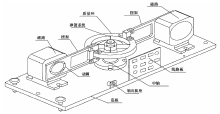
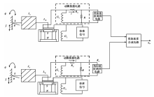
地震转动加速度传感器的机械结构如图1所示, 地震转动加速度传感器的电路原理如图2所示。在进行地震观测时, 地震转动加速度传感器的底板固定在观测点上, 当发生地震时, 地震转动加速度同时作用在底板上, 与底板相连的磁路系统、 中轴同时跟随底板同步震动, 由质量环、 摆架和动圈组成的运动部分相对于中轴产生相对转角, 安装在2个摆架上的2个工作线圈 G1、 G2相对于2个磁路的磁缝隙均产生相同的相对运动, 2个工作线圈G1、 G2 都在各自的磁缝隙中切割磁力线产生感应电动势, 各自产生的电动势分别输入至各自的无源伺服大阻尼动圈换能电路和角加速度调理电路, 2个角加速度调理电路同时输入给合成电路, 合成电路输出与地震转动加速度成正比的电压信号
 | 图 1 机械结构框图Fig. 1 Block diagram of mechanical structure. |
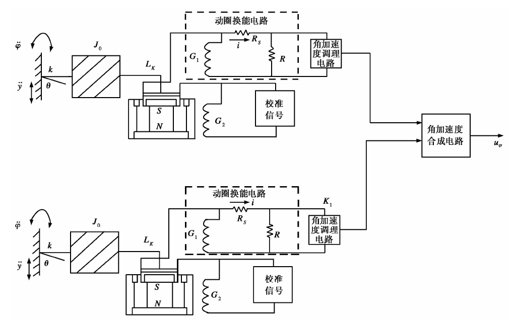 | 图 2 电路原理图Fig. 2 Circuit schematic diagram. |
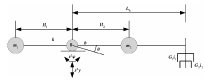
无源大阻尼地震转动加速度传感器内部结构的数学模型(杨学山, 2001)如图3所示。
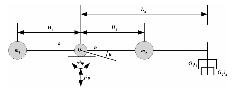 | 图 3 数学模型图Fig. 3 Mathematical model. |
图3中
当机械加工精度达到设计要求时, 即
图2所示的对称反向安装的2个摆式无源伺服大阻尼动圈换能器的电路方程式为
解方程式(1)和(2), 可得:
式中:
由式(4)可以看出, 当
对称反向安装的摆式无源伺服大阻尼动圈换能器的输出电压分别通过角加速度调理电路和角加速度合成电路后为无源伺服式大阻尼地震转动加速度传感器的输出电压:
式中
无源伺服大阻尼地震转动加速度传感器的主要技术指标如表1所示。
| 表1 无源伺服大阻尼地震转动加速度传感器的主要技术指标 Table1 Main technical specifications of passive servo large damping seismic rotational accelerometer |
下文简单介绍主要技术指标和幅频特性。
灵敏度, 单位为V/rad · s-2, 取值范围为1~10, 即通过改变图2中角加速度调理电路的参数可以改变转动加速度计的灵敏度。
量程, 单位为rad/s2, 取值范围为 10~1, 该值与灵敏度相对应, 灵敏度越低则量程越大, 灵敏度越高则量程越小, 即灵敏度为1V/rad · s-2 时, 量程为10rad/s2, 可与灵敏度相互配合来满足不同的用户需求。
通频带(Hz, -3dB), (0.7~30), 是指在(0.7~30)Hz范围内输出信号幅值衰减不超过最大值的二分之根号二倍时对应的频带宽度, 该项指标完全满足土木工程的一般需求。
水平振动的影响 ≤ 0.01(rad/s2)/(m/s2), 是指给转动加速度计输入1m/s2的水平振动信号, 转动加速度计的输出≤ 0.01rad/s2的角加速度, 说明水平振动的影响很小。
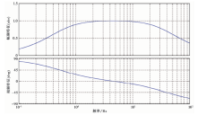
无源伺服大阻尼地震转动加速度传感器的幅频和相频特性如图4所示。
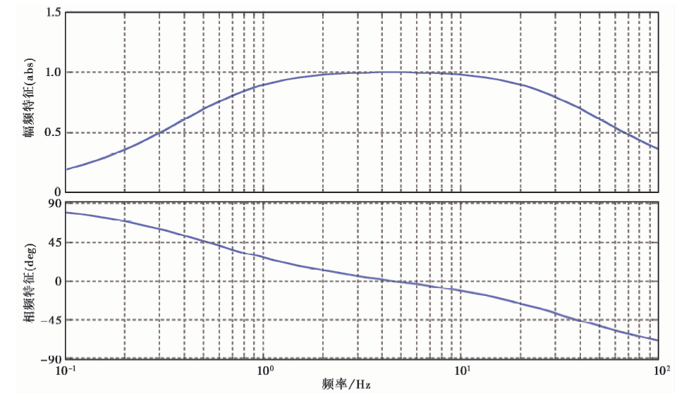 | 图 4 转动加速度传感器的频率特性Fig. 4 Frequency characteristics of rotational accelerometer. |
转动加速度传感器的幅频特性采用自校准法, 转动加速度传感器备有自校准线圈, 将信号源的输出端连接到自校准线圈的输入端, 给自校准线圈输入固定不变的电流, 改变信号源的频率, 即可获得转动加速度传感器的幅频特性, 校准结果如表2所示。
| 表2 幅频特性的测量结果 Table2 Measurement results of amplitude frequency characteristics |
转动加速度传感器的灵敏度校准采用比较法。将标准转动传感器和被校准的转动加速度传感器安装在转动振动台上, 转动振动台在信号源、 伺服控制和功率放大器的控制下产生角振动, 同时测量标准转动传感器和被校准转动加速度传感器的输出电压以及转动振动台的振动频率即可求得被校准转动加速度传感器的灵敏度。在调理系数=10时, 校准灵敏度为0.966V/rad· s-2, 改变调理系数, 可以改变其灵敏度。
2017年9月中国计量科学研究院和俄罗斯门捷列夫计量院(VNIIM)合作使用该转动加速度传感器对精密旋转振动设备的微幅振动进行了精确测量, 获得理想结果, 对测试数据进行了频谱分析处理, 分别给出了10Hz、 5Hz、3Hz、 2Hz、 1Hz、 0.5Hz、 0.1Hz等频率点的幅值, 其中部分测试结果如表3所示。测量结果符合实际情况, 该转动加速度传感器满足用户需求。
| 表3 用户测量结果 Table3 User’s measurement results |
人们早已知道地震波中的S波代表的是旋转运动状态的传播。在多次大地震的极震区, 常常会看到宏观转动破坏的现象, 地震工作者猜想这种现象同旋转有关, 但始终未能给出完备的解释。高层建筑和大跨度桥梁在风荷载作用下, 其转动分量不可忽视, 尤其是不对称荷载及电视塔等建筑, 转动分量更加明显。长期以来由于没有直接测量地震转动分量的加速度传感器, 科学工作者都是通过理论分析和计算得到转动分量。本文从转动加速度传感器的结构原理、 数学模型、 技术指标幅频特性等方面进行了研究, 分析讨论了无源伺服加速度传感器的特性, 得到如下结论:
1)无源伺服大阻尼转动加速度传感器的电路比较简单, 操作方便, 分辨率高, 适合观测地震或结构的转动加速度。
2)阻尼比越大, 转动加速度计的频率特性越宽。在机械参数固定的情况下, 阻尼比与电动常数G1和
3)通过应用实例可知该无源伺服大阻尼转动加速度传感器可以对精密旋转振动设备的微幅振动进行精确测量, 并获得理想的测量结果。
4)无源伺服大阻尼地震转动加速度传感器有助于观测地震转动分量, 以便完善地解释大地震极震区转动破坏现象和验证理论分析结果。
致谢 审稿专家对论文提出了建设性的修改意见, 在此表示衷心感谢。
The authors have declared that no competing interests exist.
| [1] |
|
| [2] |
|
| [3] |
|
| [4] |
|
| [5] |
|
| [6] |
|
| [7] |
|
| [8] |
|
| [9] |
|
| [10] |
|
| [11] |
|
| [12] |
|
| [13] |
|